Week 4, Electronics Production
This week assignment tasks are
To make an in-circuit programmer, FabISP
What is FabISP?
The FabISP is a home built AVR microcontrollers programmer, designed within a FabLab. It allows the microcontrollers on other boards to be programmed, using a USB cable and 6-pin IDC to 6-pin IDC cable. It allowed the ATtiny44 to perform USB communication through avrdude. FabISP(Right click and click Open link in new tab)
Getting Started
The components are as follows according to list provided by Neil
| Name | Part Number | Qty |
| IC MCU AVR 4K FLASH 20MHZ 14SOIC | ATTINY44A-SSU-ND | 1 |
| Bergstik Headers 2X3P UNSHRD HDR 30 | 649-95278-101A06LF | 1 |
| CRYSTAL 20.000000MHZ 8PF SMD | 644-1039-1-ND | 1 |
| DIODE ZENER 3.3V 500MW SOD-123 | BZT52C3V3-FDICT-ND | 2 |
| CAP CER 10PF 50V 5% NPO 1206 | 311-1150-1-ND | 2 |
| CAP CER 1UF 50V 10% X7R 1206 | 445-1423-1-ND | 1 |
| RES 499 OHM 1/4W 1% 1206 SMD | 311-499FRCT-ND | 1 |
| RES 100 OHM 1/4W 1% 1206 SMD | 311-100FRCT-ND | 2 |
| RES 1.00K OHM 1/4W 1% 1206 SMD | 311-1.00KFRCT-ND | 1 |
| RES 10.0K OHM 1/4W 1% 1206 SMD | 311-10.0KFRCT-ND | 1 |
| RES 0.0 OHM 1/4W 1206 SMD | 311-0.0ERCT-ND | 2 |
| CONN RECEPT MINI USB2.0 5POS | H2961CT-ND | 1 |
Getting Started
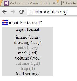
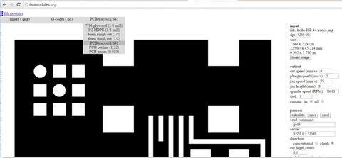
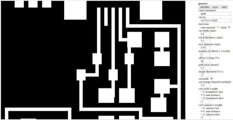
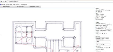
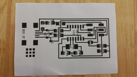
Next click here to run the fab modules.
Click on Input follow by image (.png)
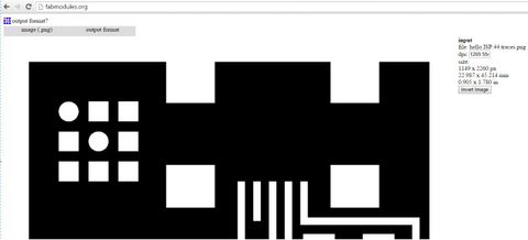
Select image.png from the folder saved
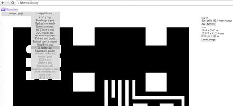
Select Gcode.nc
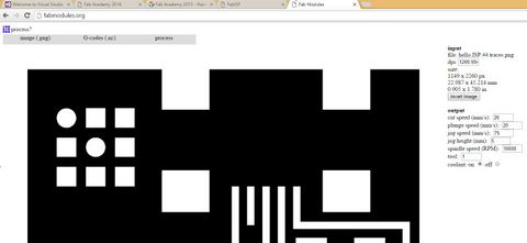
Select PCB (1/64)
Click calculate
Click save
The .NC file can be used directly with a PCB miller now.
Step 1
Step 2
Step 3
Step 4
Step 5
Step 6
Step 7
Converting files into Gerber readable to LPKF
The LPKF cannot read files from fab modules, therefore there is a need to convert .nc files in gerber files (PDF files) which is readable to LPKF.Use Paint to open the .PNG and save as .BMP using 256 color bitmap into target folder.
Once done, the procedure will be as follow:
1) Open New and Board in the EagleCAD enviroment
2) Click on the CAM Processor icon or File - CAM Processor
3) Once the CAM Processor dialog box opened, Click File - Open - Job
4) Select gerb274x.cam and OK
5) Under the Component Side tab, ensured the Top, Pads and Vias layers were selected
6) Under the Silkscreen tab, ensured the dimension layer is selected only.
7) Ensure the gerber files have a .cmp file extension in the Component Side Tab and .plc file extension in the Silkscreen CMP Tab.
8) Once OK, click on Process Job and the files generated will be saved in the EagleCAD project folder.
9) Look for filename.cmp and filename.plc
Final step is to send the .nc file to LKPF Protomat S103 machine for milling.
The procedure as follows:
1) Launch CircuitPro
2) Click on "Execute Process Planning Wizard" icon.
3) Select on template Single PCB and Component side
4) Select FR4 and Done
5) Import the filename.cmp and filename.plc
6) Ensure the layers in CircuitPro match according to those done in EagleCAD under the CircuitPro layers/template column, and click OK.
7) Create tool paths by selecting Isolating Milling.
8) Lastly, set the coordinates to 0,0 position
9) Start the PCB milling process.
Here is the link to watch the PCB milling in action.
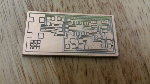
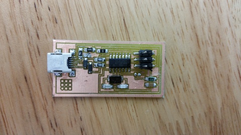
The finished PCB
Soldering the components onto the PCB
The final product.
What is the purpose of loading firmware onto the FabISP
I myself know almost nuts about all these terms. Even I can remember now, I will most likely forget everything in a few minutes time.
Therefore, for a better understanding I used these web site FabISP by David A. Mellis and FabISP Programmer by David Mellis - updated by Neil Gershenfeldfor for reference every now and then.
I still cannot understand after going through but maybe you the reader can grasp it. In any case, I just followed blindly and brainlessly.
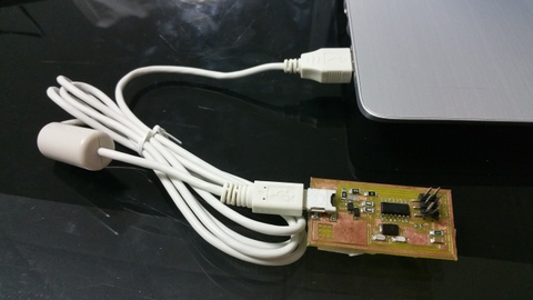
Testing the ISP
An error message appeared
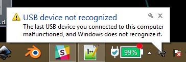
indicating the ISP is unrecongized
Double checked all connections and it turns out normal. Proceeded to make a second board but the same error message still persisted.
I ran out ideas and will leave the matter here and wait divine intervention.
Making the FabISP Board (Updates)
Next, we used an Arduino Uno and programmed it to work as an ISP in order to program FabISP.
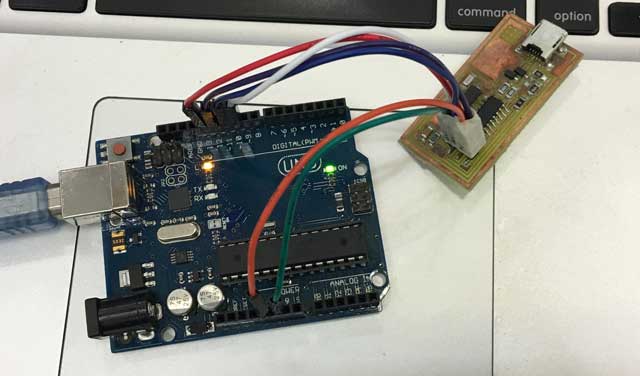
The connection between Arduino and the FabISP are as follows:
Uno ---- FABISP
10 ---- Reset
11 ---- MOSI
12 ---- MISO
13 ---- SCK
5V ---- VCC
GND ---- GND
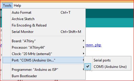
After the connction is done, start up the Arduino IDE and follow the picture below on the settings to be done.
We then visited this website to learn how to program the FabISP and to download WINAVR programmer for Windows.
It is very important to follow the steps described but I'll listed it out just in case.
Get and install avrdude / GCC software and dependencies and drivers:
1.Download and Install WinAVR
You can also go directly to this website to download the latest version.
2.After installing check your systems path variable, if it only contains the path to the winavr installation:
*copy those values
*restore your old path
*add the windavr path back to it
*close any commandprompt window you may have open
3.Download the drivers for your version of Windows
4.Download FabISP Firmwarehere.
5.Plug in another FabISP or USBtiny programmer
6.Install the drivers as instructions that follows:
*Go to the Start menu -> Control Panel -> Device Manager (or run "mmc devmgmt.msc") ◦Locate "FabISP" under "Other Devices"
*Right click on the "FabISP"
*Select "Update Driver Software.."
*Select "Browse my computer"
*Navigate to the drivers folder you downloaded at step 4 and click on the folder
*Hit "ok" to install the drivers for the USBtiny / FabISP
Now is to powerup the board and edit the Makefile
The commands edit the Make file to such are as follows:
AVRDUDE = avrdude -c usbtiny -p $(DEVICE) # edit this line for your programmer
#AVRDUDE = avrdude -c avrisp2 -P usb -p $(DEVICE) # edit this line for your programmer
Then compile the firmware in the command terminal by using:
make clean
make hex
make fuse - this will allow the ISP to use external crystal
make program
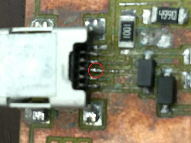
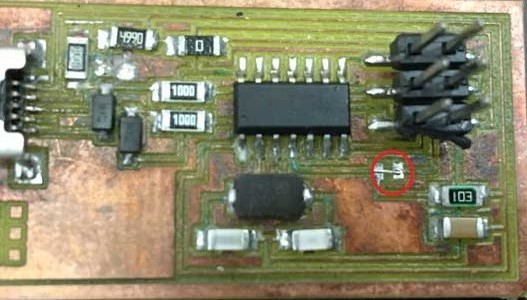
Finally removed the jumper as shown
Testing the fabisp to see if it works
1. Download FabISP driver from here and save it in a convenient location and EXTRACT the .zip file.
2. Connect the FabISP via mini USB to a laptop.
i. START --- Search for DEVICE MANAGER --- OTHER DEVICES
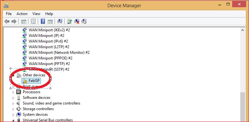
The com port will detect FabISP with a question mark.
3. Right click to update the driver software and ENTER.
4. USBisp will appear.
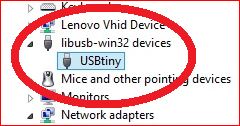
Now the board can be used to program other boards.
My Comments
Soldering the components were really very challenging. The components were really small and extremely difficult to perform surface mount soldering on them.
This sets me wondering whether the amount of money saved by making your own ISP really worth the effort and time? The difference in pricing could have been brought to do more meaningful task.